


NASA is seeking to challenge the GrabCAD Community to design an ultralightstarshade structure to support the proposed NASA Advanced Innovative Concepts (NIAC) study called the Hybrid Observatory for Earth-like Exoplanets (HOEE). The HOEE study team seeks ultralightweight structural concepts for a starshade that could help determine if there is life on planets around other stars.
Observing reflected light from Earth-like planets orbiting Sun-like stars is a top priority for astronomers and for NASA. An orbiting starshade (170,000 km away) could cast a shadow of the central star without blocking the reflected light from its planets. So that it can be used with the largest ground-based telescopes, the starshade needs to be 100 m in diameter. This large structure must be tightly packaged so that it can fit inside the fairing of a large rocket (e.g., Falcon Heavy or Starship). It must also have the lowest possible mass so that chemical thrusters can keep it aligned during observations and solar electric propulsion system can change its orbit to observe many targets. NASA seeks breakthrough mechanical/structural concepts for a deployable, low mass, high stability, and high stiffness starshade structure.
Technical Background
Starshades can cast deep shadows of the target star if they are properly shaped to manage diffraction. The optimal shape has a central dark region surrounded by tapered petals. Originally it was thought that only telescope/starshade combinations in outer space could achieve adequate performance. But with the 30 m class telescopes (GMT, TMT, and ELT) currently under construction on Earth and high-performance single conjugate adaptive optics (SCAO) at visible wavelengths, it will be feasible to make these observations from the ground. These large telescopes enable the Hybrid Observatory concept, with a starshade orbiting in space and a telescope on the ground. The starshade must maneuver to be precisely on the line from target star to the telescope, matching both position and velocity, and must accelerate to stay on this line as the Earth (and observatory)rotates,. If such a system could be built, it could image a solar system in 1 minute at a distance of 5 parsecs and obtain planetary spectra with oxygen and water in 1 hour. A spectrum like the Earth’s would provide a strong indication that life is present on the planet being observed. Such a hybrid observatory could have an observing speed 1000x greater than a 6 m space telescope, as well as produce images with 6x better angular resolution. The orbit choice is a solved problem: a high ellipse with an apogee of at least 170,000 km, so the starshade can match velocity with the observatory as the Earth rotates.
The complete starshade is a spacecraft with all the systems a typical spacecraft requires. A key challenge for a cost-effective starshade system is caused by the rocket equation which governs two things: how long the starshade spacecraft can match the acceleration of the observatory and how many times its orbit can be adjusted to enable observations of different target stars. The first is managed with chemical propulsion. The second is managed with high Isp (specific impulse) solar electric propulsion. In both cases the scientific yield is roughly proportional to the achievable velocity changes. The upshot is that a low starshade structural mass is critical for a cost-effective mission. NASA hopes that the GrabCAD community can help develop innovative structural concepts to reduce the overall mass of the starshade structure.
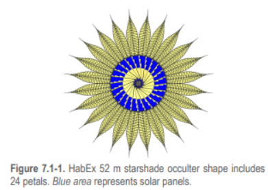
Starshade designs were developed at JPL for space-based telescopes like the Nancy Grace Roman Space Telescope and the proposed HabEx mission. Details on the design can be found on the websites listed later in the challenge description.
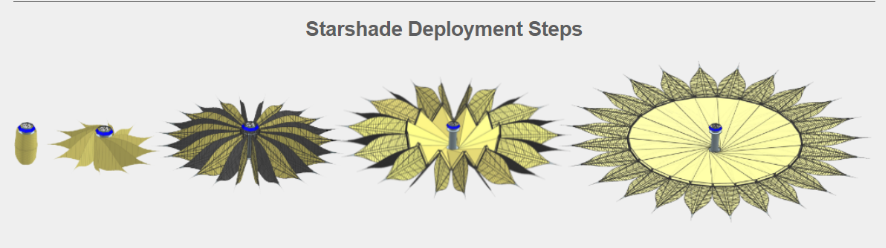
There is little doubt that the 50 m diameter starshade required for a space telescope could be built and launched for a 6 m class space telescope. However, extrapolating the current 50 m diameter starshade design to a 100 m scale for use with a 30 m ground telescope showed that the mass and volume were too high for even a Falcon Heavy rocket if adequate propellant for maneuvering was added. We therefore seek alternate concepts. Such concepts include radical light weighting of the JPL concept; a deployable umbrella with petals; a rigidizable inflatable structure; and an ultralight truss, perhaps assembled in space by robots or astronauts. We are inspired by the Eiffel Tower, which is a third-order hierarchical structure, in which truss elements are themselves trusses, etc. Much work has been done on in-space assembly as well, and indeed there is a new National Strategy for it that could lead to implementation.
The goal of this challenge is to develop an innovative low-mass starshade structure that could meet the mass, shape, strength, and stiffness requirements. Solvers can consider one of these categories or a hybrid design.
1. Ultralight version of the current JPL HabEx concept
2. Umbrella with petals
3. Rigidizable inflated structure
4. Truss-based structures
In addition to being very lightweight, the ideal starshade design should be self-deployable (although we are interested in other options), and allow for compact packaging. NASA is looking for innovative packaging and deployment methods that can reliably deploy the starshade system after being placed in Earth orbit. We seek ideas to complement our studies currently in progress, hence the challenge. Our highest priority is lower mass.
Below are example designs from the HabEx final report
Requirements
Key physical requirements are:
1. The starshade structural mass including opaque membranes shall be less than 1000 kg. (Since the estimated mission cost is roughly proportional to this mass.) This mass target does not include the central hub, spacecraft bus, propulsion system, solar arrays, and power supply.
2. The starshade casts a shadow of the star based on the shape of a flat surface. In order to detect light from extrasolar planets, it is critical that reflected sunlight does not saturate the detectors. Reinforcing structures may project above or below this flat surface, with some restrictions. In use, the starshade plane may be tilted up to 30 degrees from being perpendicular to the line of sight to the telescope. The line perpendicular to the starshade plane may also be oriented at angles from the Sun ranging from 40 to 80 degrees, so the Sun is only 10 degrees above the starshade plane. In all these cases, during observations, no sunlight may strike any part that is visible to the telescope, except the sharp edges. (This is to ensure the widest range of useful angles between the Sun and the target star.). See the illustrative figure below. To construct the excluded volume above the starshade, construct a cone with a vertex on the boundary, open upwards, and half-angle of 30 degrees, and move it around the boundary of the starshade. To construct the excluded volume below the starshade, do the same but open downwards, with a vertex half angle of 80 degrees.
3. To minimize sunlight scattered towards the telescope, the starshade petal edges must be sharp, thinner than paper. Therefore the packaging and deployment or assembly process must protect all parts from damage.
4. When fully deployed, the starshade shall withstand accelerations of 0.03 g’s in the axial (out of plane) and lateral (in plane) directions. Starshade must recover its zero-g shape within tolerances within 10 seconds or less. This is to match the observatory acceleration of up to 0.003 g, using pulses from the rocket. The rocket thrust to maintain alignment during observation will be pulsed with a roughly 1-minute period and a duty cycle <10%, because the jets themselves are bright enough to interfere with observations. Hence, rapid recovery from transient acceleration is required. Note that this requirement also implies that the starshade could be constructed or assembled in low Earth orbit if desired, and could withstand the force of a small booster to reach the high orbit needed for observations.
5. The deployed starshade shall accommodate an empty cylinder 2 m in diameter in the center, open on both ends (This is reserved for the spacecraft bus and propellant tanks.) The rocket jets should be assumed to be on both ends of this tube and oriented to avoid direct impingement on the starshade itself. Normally they will be fired in balanced pairs to avoid undesired torques, but they can also be used to produce any necessary torques to re-orient the starshade. Protecting the starshade material from the jets is outside the scope of this study. See graphic below.
6. The starshade structure shall support a mission duration of 3 years (prime mission) with a preferred goal of 4 x 3 years with 3 refueling visits. This requirement means that an inflatable system must be rigidized or have a very
good leak control, given the expected number of micrometeoroid impacts based on statistical analysis.
7. The starshade shall have a central disk of 25 m radius
8. The starshade shall have at least 24 petals, each being 25 m long. (See basic HabEx design.)
9. In zero gravity during observations, the starshade shall have an edge shape tolerance of 5 mm with petal position tolerance / in plane deflection of 5 cm (This is looser than for smaller telescopes and smaller starshades.) Petals are
allowed to move out of plane by 1 meter as long as the shadow has the right shape within tolerances, and the sun does not illuminate parts seen by the telescope.
10. The packaged starshade (including central cylinder) should fit into a cylindrical package that is 14 m long by 4.5 m in diameter. (This is approximate and is based on the extended fairing static envelope specified in figure 12-10 of the Falcon Payload Users Guide. If targeting a different Launch Vehicle or performing in-space assembly, provide your assumptions.)
11. When in a packaged configuration, the Starshade must be capable of surviving launch loads. (High levels of vibration/acoustics could damage some brittle materials.)
12. Analysis:
a. Performing Structural analysis as part of your design process using hand calculations is highly recommended. Show Free Body diagram with forces involved and use formulas from Roark & Young, Timoshenko, Shigley, and other structural analysis references to show how you solve for loads, stiffness, buckling, stresses and fundamental frequencies of the components of your Starshade concept as needed, to show compliance with the requirements. A full Finite Element Model exceeds the scope of this competition and is not required, but if you
have the time and want you may create one.
b. International system of units (kg, m, sec, K) shall be used in analysis calculations. Angles shall be reported in degrees.
c. The following coordinate system shall be used when performing analysis and calculations
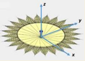
d. Use Load factors of 0.03 in the X, Y (lateral) and Z axial directions (corresponding to the 0.03 g’s axial and lateral acceleration case).
e. Minimum deployed frequency/stiffness: design the Starshade with axial, lateral, bending, and torsional stiffnesses such that during observations, the maximum in-plane petal deflection is +/- 5 cm and the maximum allowed out-of-plane petal deflection is +/- 1 m. After any disturbances, Starshade shall recover its zero-g shape within tolerances in 10 seconds or less.
f. Factors of safety of 1.25 (yield) and 1.4 (ultimate) for metallic structures and 1.4 (ultimate) for composite/bonded structures shall be applied to the limit loads to determine the yield and ultimate design loads and show positive margins of safety on strength.
Example:
1. Axial limit load factor nz = 0.03
2. Limit load (axial) = 1000 kg * 0.03g’s = 294.2 N
3. Design ultimate Load (axial) = 1.4* 294.2 = 411.9 N
4. Margin of Safety on ultimate axial loads= Allowable Load
(or stress) / Design Load (or stress) – 1 > 0 to satisfy
design criteria.
g. For kinematic deployments consider showing your kinematic analysis as well as forces involved during the deployment.
It is recognized that there are many more requirements for a flight system, such as shape accuracy for the shadow, thermal stability, opacity of the starshade after micrometeoroid impacts, and sun glints from the edges. Here we concentrate primarily on the mechanical concept and emphasize its mass.
A successful outcome of this contest will include 3D models and graphics, and/or animations of an ultra-lightweight starshade structure. These may be used to communicate the different concepts in the NIAC study report and may be considered for further development in future studies. It is understood that meeting all requirements at once is very challenging and partial success is still valuable.
Starshade design challenge submissions must include:
1. CAD models of a deployed starshade structure (Submissions to be provided in STEP or IGES file formats).
2. Proof that the Sun does not illuminate structures visible to the telescope, except for the sharp edges.
3. Include a concept for packaging the starshade system that shows a feasible method of deployment from a packaged state. This may be provided in 2D drawings or as 3D animations.
4. Provide an estimate of the starshade structural subsystem mass and packaged (stowed)/deployed dimensions.
5. Discussion of why and how the concept meets the stiffness and strength requirements. A structural analysis based on the CAD design will be very valuable. Any supplemental documents such as structural analysis shall be in PDF format.
Concept submissions should discuss scaling laws that describe the mass, stiffness, and strength as a function of major design parameters and choice of materials. In
particular, what materials or design changes should be used in a smaller-scale (1, 3, 10, or 30 m) physical model, to emulate the performance of the 100 m system?
We want to hear your ideas! The solver should discuss the feasibility of a self- deploying system versus in-space assembly in an attached description of the concept.
For this contest, a graphic showing the HabEx starshade design has been provided as a starting point. When scaled up to a 100 m diameter, the HabEx design will not meet the mass requirements for the Hybrid mission concept so an alternate design must be considered.
Ideas that should be excluded:
1. Avoid concepts that require extensive human or robotic support for assembly and/or deployment since this would greatly increase the cost of the mission, at
least in today’s environment.
2. Avoid concepts that are extremely complex as this adversely impacts fabrication, reliability, and increases mission risk.
3. Avoid concepts that require technologies that have a very low technology readiness level since this greatly increases development risks.
Design Notes from the challenge owner:
It is common to assume that to make something stronger and stiffer, we should increase its mass. But this intuition fails when the item being strengthened is its own
mass load. We expect that ingenuity is required in suitable geometric shapes that are naturally strong and stiff, and not subject to Euler buckling. It is hoped that a winning concept will be sufficiently robust that deployment on the ground does not require perfect g-negation (gravity compensation) systems.
We note that ultralight space structures are rarely stiff enough to meet our requirements, and our structure needs substantial thickness. The lowest mode frequency of an unsupported flat bar is about f = c(T/L 2 ) where c is the speed of sound, equal to (E/ρ) 1/2 , where E is the Young’s modulus and ρ is the density. T is the thickness, and L is the length. If c = 5000 m/s (e.g. aluminum) and T is 0.3 m and L is 71 m, then f is about 0.3 Hz. We need a way to remove most of the material, while maintaining a high specific stiffness, and increase the damping, so that vibrations die out quickly. Hence, the GrabCAD challenge! Also, deformation under acceleration scales as a(m/k) where a is the acceleration, m is a mass, and k is the stiffness. A mode frequency for a mass on a spring is (1/2π)(k/m) 1/2 so the deformation under acceleration is of order a/(2π f) 2 . If a = 0.03 g, f = 0.3 Hz, then the deformation is only 8 cm. Our structure must be very stiff, more like a bridge than a solar sail. Note that 0.3 Hz is not a requirement, only an example.
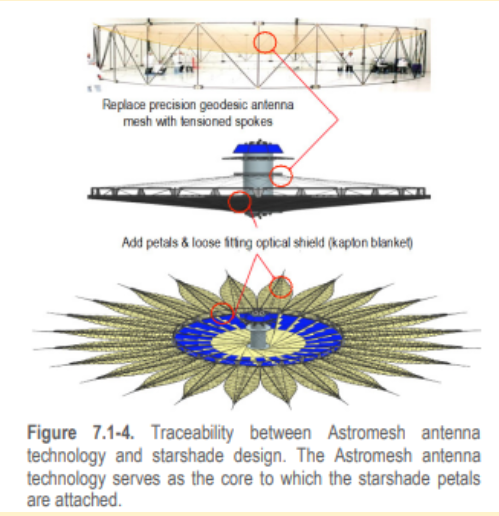
One design category is an improvement of the HabEx design, which already includes concepts for packaging and deployment, and edge protection.
Re-use of existing inventions is highly desirable. Extensive work has already been done on hierarchical materials, inflatable structures, coilable booms, artificial intelligence, and genetic algorithms to remove unnecessary mass. Many studies have been done on in-space assembly and construction, but few structures have been required to tolerate significant acceleration after completion.
Similarly, the natural world has remarkable examples of ultralight structures, ranging from hollow bird and dinosaur bones, dragonfly wings, to feathers, to composite materials like wood and bamboo. Engineered ultralight systems have been developed for human-powered aircraft, for radio antennas, and for racing yacht masts. Self-erecting cranes are segmented trusses engineered for high strength and low mass.
Awards:-
$7000 in Total Prizes
$7000 in Total Prizes
First Place
$3000
Second Place
$2000
Third Place
$1000
Fourth Place
$750
Fifth Place
Deadline:- 22-08-2022


